Home-Made Magnetic Loop Antenna for 30
Meters
A "magnetic loop" antenna, so named because it responds
primarily to the magnetic rather than electrical component of a radio wave, is a
very small (relative to wavelength) single-turn loop tuned to resonance with a
series capacitor. A second, much smaller loop connected directly to a coax
feed line is placed inside the larger loop, near the side opposite the
capacitor. This small loop forms the primary winding of an air-core RF
transformer, with the larger loop forming the secondary winding. The MFJ
"Super-HI-Q Loop" antenna and the old AEA "IsoLoop" are commercial versions of
such an antenna that use a variable capacitor to tune the antenna between 10 and
30 MHz.
See this Wikipedia article for a good discussion on loop
antennas:
<http://en.wikipedia.org/wiki/Loop_antenna>
This type of antenna is self-contained. It does not
depend on a ground plane or radials, making it ideal for portable or temporary
operation. Unlike a vertical, the antenna produces high-angle as well
as low-angle radiation, making it useful for NVIS (Near Vertical Incidence
Skywave) short-haul communications as well as DX.
 In
free space (i.e. over a half-wave above ground), the horizontal low-angle
radiation pattern is a figure-8 similar to a dipole antenna. Unlike a dipole,
the maximum radiation is off the edges of the loop, not the broadside. The
high-angle NVIS pattern is nearly omni-directional.
In
free space (i.e. over a half-wave above ground), the horizontal low-angle
radiation pattern is a figure-8 similar to a dipole antenna. Unlike a dipole,
the maximum radiation is off the edges of the loop, not the broadside. The
high-angle NVIS pattern is nearly omni-directional.
In typical portable use on a short mast near the ground (or as an attic stealth
antenna) the pattern will be distorted and nearly omni-directional at all
vertical angles. The figure-8 will "fatten" so that the "nulls" are only 2-3 db
down from the main lobes.
Such a device can be nearly as efficient on transmit as
a full-sized dipole -IF- the loop conductor and capacitor are very low loss. Any electrically-small antenna (i.e. dimensions that are a small
fraction of a wavelength) will have an extremely low radiation resistance, often
far less than a tenth of an ohm. The DC resistance of the conductor often is far
greater than the radiation resistance, unless very heavy-gauge wire or tubing is
used for the loop, and the number of joints are kept to the absolute minimum.
With a 100 watt transmitter, HUNDREDS of RF amps circulate in the loop.
Normally, magnetic loop antennas use motorized
high-voltage butterfly, split-stator or vacuum variable capacitors to remotely
tune the loop to resonance over several bands, while withstanding the very high
RF voltages (4,000 or more volts) that appear across the capacitor at 100W
transmit power levels. The kind of high-voltage capacitors used in high-power
antenna tuners are required.
A useful calculator for determining the capacitance to
resonate a loop of a given size, and to estimate the efficiency, RF currents and
RF voltages to be expected is downloadable from this website:
http://www.magneticloopantenna.com/
Click on the "Software" button near the upper-left corner of the page.
| Update as of 15 November 2011
The magneticloopantenna.com website
seems to have disappeared from the Internet. The calculator referred
to above is now downloadable from this website. This is a single-file
ready-to-run .EXE file. No install is required. Just download and run
it.
<http://wa8lmf.net/miscinfo/KI6GD-LoopCalc-1.6.exe> |
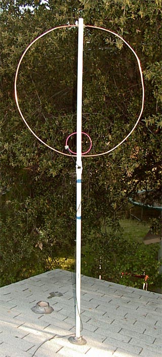
This design is a single-frequency loop for 30-meter HF APRS
operation (details here) which
takes place on 10.149 MHz . It is constructed of 3/8-inch soft copper "refrigeration tubing"
readily available from
Home Depot. Ten feet (308 cm) of this tubing are bent into a
circular loop about 38 inches (97 cm) in diameter. The soft tubing is easily
bent and formed by hand. The vertical supporting mast and insulator
is made from a piece of 1" (2.54 cm) Schedule 40 PVC water pipe. with two holes drilled
through it's diameter about 38" (96.5 cm) apart. The holes are drilled and
reamed to be a size such that the copper tubing force-fits snugly through them.
The tubing is stiff enough to retain it's shape without horizontal cross arms.
Note: Increasing the copper tubing size
from 3/8-inch to 3/4-inch diameter and lengthening the loop circumference to 12
feet (20% increase) will double the radiation efficiency from about 20%
to around 40% (relative to a full-size dipole). But you would have to give
up the exceptionally easy-to-make capacitor assembly described below.
On receive, the difference in performance is non-existent because the 30M band
is so noisy most of the time. The limiting factor on receive at 10 MHz is
natural noise, not antenna efficiency. The 3 dB efficiency increase is only
apparent on transmit. For receive-only APRS monitoring or igate duty, the
smaller version will work as well as the larger one.
The 10-foot piece of pipe is cut into two pieces and
then rejoined with a pipe cross-tee, allowing the antenna to be disassembled to
fit into the trunk of a car.
I didn't need the antenna to be tunable since it will operate on a single spot
frequency (10.149 MHz) permanently. I calculated the required capacitance
required to resonate the loop at 10.15 MHz using the calculator referred to
above, and
set out to create a cheap fixed-value capacitor with 4-5 KV breakdown voltage.
The inside diameter of the 3/8" tubing is an EXACT fit
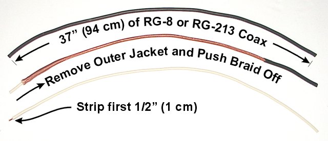
for the center conductor and dielectric of RG-8 or RG-213 coax.
Strip the outer jacket and braid off 37 inches (94 cm) of RG-213 cable and then
strip the dielectric off half an inch (1 cm) of the remaining insulated center
conductor.
Solder the exposed half-inch of the cable to the INSIDE of one
end of the loop tubing. You'll need a old-fashioned 150-watt soldering
iron or a Bernz-O-Matic propane torch to heat up the copper tubing (not a wimpy
electronics pencil or temperature-controlled soldering station) since the copper
is such a good conductor of heat. Push the remaining 36 1/2" of
dielectric-covered center conductor into the open other end of the copper
tubing. Push it in until the loop is nearly closed with only a
1/4-to-3/8ths-inch gap between the two ends.
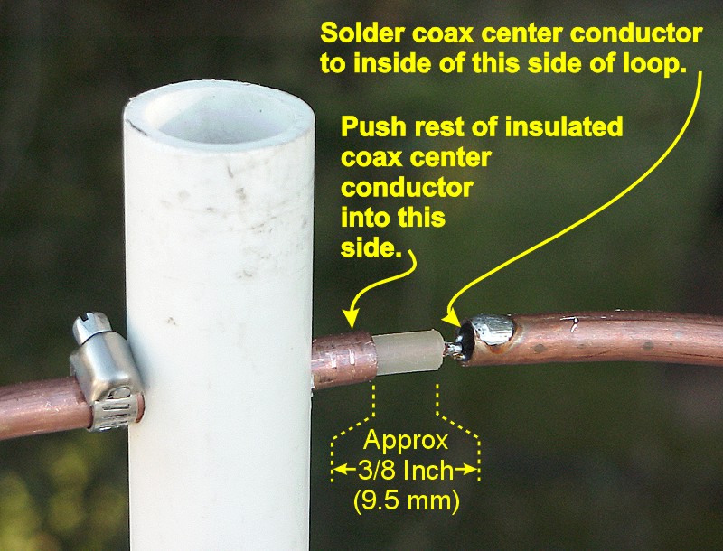
This construction creates a coaxial capacitor with the
coax cable center conductor being one plate and the INSIDE of the copper tubing
being the other plate of a capacitor. The 36" or so of cable inside the tubing
creates a capacitance of about 75pF, required to resonate the loop at 10.15 MHz.
Normal 50-ohm coax has a capacitance of about 30-33 pF/foot. The snug fit
between the center conductor/dielectric, and the inside diameter of the tubing,
very closely duplicates the geometry, and thus capacitance per foot of the original coax
. (You could literally make your own copper hardline from this tubing by
pushing yards and yards of center conductor/dielectric from RG/8, RG/213 or RG/214
into it.)
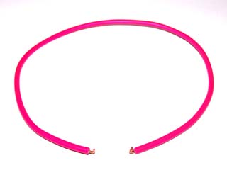
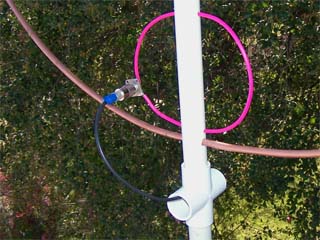
Finally, create the coupling loop. Cut 21" (53.5 cm) of
normal #14 copper house wire & form it into a loop approximately 7 inches
(17.8 cm) diameter. Solder one end to one of the holes in the flange of a coax socket. The
other end will be soldered to the center pin of the socket after the
wire is threaded through holes in the supporting mast.
Click on small pictures for larger view in separate
browser/tab.
This loop is then placed so that it is
about 1/2-inch (1.2 cm) away from the inside circumference of the large loop on
the side opposite the open-ends & capacitor. Drill two holes holes
through the diameter of the PVC pipe to support the small loop in the proper
orientation. Thread the free end of the loop wire through the two holes
and then solder the end to the coax socket center pin.
The loop is tuned to exact resonance by
pulling the top of the loop apart, or pushing the loop together exposing more or
less of the coax cable dielectric/center conductor. (Only the portion of the coax opposite the tubing's
inside diameter contributes to the capacitor's value.) I had to expose about
3/8" of the dielectric to tune the antenna to 10.149 MHz. The tuning is VERY
sharp (indicating hi Q and high efficiency). A change of 1/8th-inch (3 mm)
moves the resonance about 100Kz. The bandwidth for 2:1 SWR is only about 12
KHz. This is actually an advantage for single frequency operation; the antenna
is so selective that transmitting on other HF bands from other nearby antennas
won't desensitize the 30-meter receiver at all.
Bend the small loop (distorting the circle)
so that more or less of it is closely parallel to the big loop to fine-tune the
SWR at resonance. Mine has an SWR of under 1.3:1 at resonance. Unlike the usual
dipole or vertical, his antenna is relatively unaffected by it's surroundings. I
tuned it on the ground with the pipe mast lashed to a stepladder. After moving
the antenna to it's final location on the roof-top, the tuning did not change at
all.
The antenna mast/support is constructed
from a single 10-foot (308 cm) length of PVC pipe. The outside diameter of the
1" plastic water pipe is an almost perfect fit for bathroom and kitchen drain
pipe vents on the roof. I inserted the pipe about 3 feet (1 m) into
a vent pipe, and placed a hose clamp around it to keep the mast from falling
further into the vent.
Alternatively, this antenna could be used
for a "stealth" installation in an attic crawl space by sawing off enough of the
plastic pipe mast to fit. Note that an attic install will not work well if
you have aluminum-skinned insulation on the underside of the roof (or a metal
roof).