| WA8LMF Home Page | Useful Links | Main Ham Radio Page | Updated 06 April 2023 |
[The content on this page is also downloadable as a 3-page PDF file, useful for printing the diagrams as worksheets for wiring cable assemblies. CLICK HERE to download.]
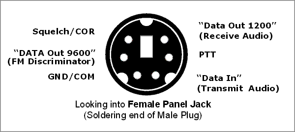
The 6-Pin MIniDIN jack is a standard used by all the Japanese ham equipment manufacturers. Many current all-band all-mode and VHF/UHF-FM transceivers are equipped with this jack.
This jack is variously called "data", "packet", "auxiliary", etc, but actually there are no data connections on this connector. This IS NOT a RS-232 serial data, USB, or RTTY direct FSK port. Only various forms of receive and transmit audio are present. The connector provides receive audio output at a fixed level of about 100-300mV, transmit audio input at about the same level, transmit PTT keying, receiver squelch status (COR), and ground/common.
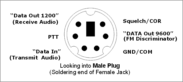
The normal RX audio line a.k.a."1200 baud packet", is live on both FM and SSB in multimode transceivers. It is sometimes labeled "1200 baud packet". However, the output is just standard receiver audio (de-emphasized on FM) similar to what comes out the radio’s speaker. Output level is fixed, unaffected by the volume control.
The audio at this point is suitable for any voice-frequency-band application such as sound card interfaces (for SSTV, Echolink/IRLP, PSK31, RTTY, etc), VARA HF and VARA FM Slow Mode, mutimode data controllers for Pactor, 1200 baud packet TNCs, phone patches, APRS trackers, DTMF and paging encoders/decoders/selective calls, etc.
The audio levels into and out-of this connector are similar to home stereo audio “line level” connections at RCA jacks on amplifiers, tuners, CD players, etc. The levels are also a perfect match for the levels on 3.5mm computer sound card “Line Out” and “Line In” (not Mic input!) jacks. No attenuator pads or voltage dividers are required.
Normally computer sound systems must have at least three 3.5mm mini-jacks present to offer the proper line-level input. The picture below shows the standard 3-jack audio panel
|
Standard 3-jack audio panel present on many desktop computers. The color-coding is always the same: green for "Speaker/Line Out", pink for "Mic-In", and blue for "Line In". Note that many newer PCs and most laptops have only two jacks: the green "Line Out" and the pink "Mic-In". |
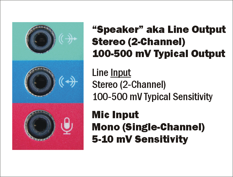 |
Trying to couple the much-higher-level receive audio of the mini-DIN data jack directly into a MIC input will almost always result in overloading the mic preamp inside the PC, yielding severe distortion of the incoming audio. An audio attenuator (voltage divider) of somewhere between 10:1 and 50:1 is normally required. Further, the Mic-In jack is always monophonic, despite the three-conductor “stereo” jack. Audio is normally input through the ring contact of the jack, while the tip contact carries 5-8 VDC power from the PC to power amplified electret microphones.
The single “Transmit Audio” pin is used for both 1200 baud packet (and narrowband audio for other modes), and for 9600 baud wide-band packet The pin’s function is usually switched from the normal millivolts-of-audio mode to DC-coupled volts-of-data, by a setup menu option in radios that support this mode.
On some VHF/UHF radios, a menu option can switch the single transmit input pin from the usual all-mode (FM VHF/UHF and SSB) narrow-band modes to the wide-band mode required for 9600-baud packet or VARA FM Fast mode. If this option exists, you can normally leave it set in the wide-band "9600" mode even for modes like SSTV, 1200-baud packet; i.e. APRS, etc.
Because the "9600" mode does not apply transmit pre-emphasis, audio bandwidth limiting or deviation limiting, it is not suitable for voice applications such as EchoLink, IRLP, etc.
The 9600-baud/wideband TX mode only exists on FM -- there will be no signal transmitted from all-mode radios in the SSB or AM mode, if the menu setting is in the "9600 TX" mode.
The “COR”, “Squelch” or “CD” pin is a 0/5-volt logic-level signal that follows the state of any “Busy” or “RX” indicator light on the radio’s front panel. It can be used to inhibit transmit by APRS trackers, Echolink interfaces, TNCs, etc when the radio channel is busy.
The “PTT” pin (confusingly labeled “Standby” on many Kenwood radios) is a normal ground-to-transmit line. On most radios, grounding this line to transmit also automatically mutes the front panel mic input to prevent extraneous audio pickup from the microphone from corrupting transmitted data.
On radios with FM, the 6th pin, often labeled “9600 Baud”, is a DC-coupled connection directly to the receiver’s FM discriminator. The NON-demphasized alway-on non-squelched wide-band audio at this point is normally used for receive by 9600 baud packet modes, or for the VARA FM Fast Mode.
IMPORTANT: There are some significant inconsistencies in the way radio manufacturers are
implementing this jack. The standard calls for the "1200 baud" RX pin to
be de-emphasized & squelched (i.e. "speaker-like") audio, while the
"9600 baud" receive pin is supposed to be a flat (non de-emphasized) non-squelched
always-on direct connection to the radio's FM discriminator.
On one radio I tested, both the "1200 baud" RX pin and the "9600
baud" RX pin carry raw discriminator audio. The only difference is that
the "1200-baud" pin is squelched while the "9600-baud" pin is always on.
On another, the "1200-baud" pin properly carries de-emphasized audio while the
"9600-baud" pin carries the proper flat raw discriminator audio --BUT-- both are
squelched. (This defeats the whole point of the "9600-baud" pin,
which is to be able to feed audio into a TNC open squelch for the utmost
sensitivity while being able to mute the radio's speaker for monitoring.)
Check your ports before using -- YMMV.
The 6-pin mini-DIN plug and connector are also commonly known as “PS/2” connectors when used for keyboard and mouse connections on computers. (This connector was first widely used on the IBM PS/2 family of personal computers in the mid-to-late 1980s. It has continued to be used for this purpose industry-wide, until USB-interfaced mice and keyboards started appearing in the mid-2000s.)
Note that cables salvaged from dead mice and keyboards often only have 4 of the 6 pins wired. On the other hand, keyboard/mouse PS/2 “extension cords”, available at most computer supply stores, normally have all six conductors present.
Such extension cords are a good source of ready-made cable assemblies for the ham mini-DIN jack. Cut an extension cord in half. Use the end with a male plug to make up connecting cables for TNCs, soundcard interfaces, APRS trackers, etc. The resulting cable assembly is identical to the so-called “data cables” sold by the ham manufacturers for up to $35.
Solder the leads of the half with a female inline jack to a male 13-pin full-size DIN plug. This creates an adapter that converts from the ACC2 jack on Kenwood HF transceivers to the standard mini-DIN 6 female jack. In turn, this allows you to use the same hardware cabled for use with mini-DIN6 -equipped radios, with Kenwood HF radios.
Finally, the PS/2 jack, in it’s original
usage on computers, is a convenient source of 5 volts DC power for small devices
such as GPS receivers or cell phones.
The external keyboard/mouse connector of this type present on some laptops is
often used to steal +5 VDC power from the laptop's power system for an external
serial GPS unit. Before USB, older serial GPS units often had a forked cable
with a DB9 plug for serial data and a PS/2 plug for power.
(Current USB GPS receivers don’t need the forked cable, since USB ports
inherently can supply up to 500mA at 5 VDC to power the device at the other end
of the USB cable.)