| WA8LMF Home Page | Main Ham Page | Updated 13 December 2015 |
Sound Card Interface with Tone Keyer |
Jump to: Photos Schematics Downloads lower down on this page.
This is an improved version of the audio interface commonly used to connect a computer
soundcard to a transceiver's receive and transmit audio circuits. This kind of interface
is used by computer programs that send and receive SSTV, RTTY, CW, PSK31 and various other
digital modes entirely in software.
Soundcard interfaces are not data controllers, TNCs, decoders or signal
processors.
They merely:
The usual version of this type of interface (including the commercial
"RigBlaster" and MFJ units) requires a computer serial port to provide PTT
(push-to-talk) control for the radio's transmitter. This type of control uses only the
RS-232 RTS and DTR handshaking lines; the actual TXD and RXD data lines themselves
are not even used!
This version includes an audio tone detector that keys the transmitter whenever transmit
audio is generated by the application running on the PC. No serial port connection
is required; a major advantage since modern PCs increasingly lack serial ports. One is forced to use the chronically problematic
serial<-->USB converter cables a.k.a. "dongles".
The audio coupling is normally done with audio transformers to avoid a common ground
connection between the computer and radio. This prevents ground loops which can cause hum
and feedback on transmit.
NOTE: A common mistake in soundcard-interface construction is to use an
8-ohm-to-10K transformer for the receiver-to-soundcard-line-input connection. The
incorrect assumption is that the 8-ohm speaker impedance needs to be "matched"
to the sound card Hi-Z input. You are trying to couple voltage, not maximize power
transfer (the condition where impedance matching is required). All that happens is that
the roughly 30:1 turns ratio (turns ratio is the square root of the impedance ratio) of
such a transformer causes a 30:1 voltage stepup, delivering FAR more signal level (several
volts of audio) at the computer than is required. The soundcard input stage will overload,
and make the onscreen level control almost impossible to adjust (the optimum level will
wind up somewhere between zero and the first step on the Windows control panel slider!).
The audio levels at a radio's speaker terminal or the rear panel "packet",
"data", or Kenwood 13-pin ACC jacks are already at the right level (about .1 to
.5 volts ); all that is required is isolation. The classic 1:1 ratio 600-ohm-to-600-ohm
audio "line" transformer is exactly what you want. If you have to use a mic
input (many laptop computers don't have a line-level input), you will probably have to
provide a 10:1 or 20:1 voltage divider network to reduce the receive audio level.
If transmit audio is being inserted into the transceiver via the mic jack, an attenuator
network is required. This network reduces the 300-500 millivolt audio level normally
output by the sound card to the 5-10 millivolt level required by most radio mic inputs.
On SSTV, voice transmission alternates with sound-card-generated data. In this design, the
second set of poles on the double-pole double-throw PTT relay disconnect the mic and
connect the soundcard output, whenever a computer-generated tone is detected.
Many current transceivers have an 8-pin Mic jack with fixed low-level receive audio on one
of its pins, and 8 volts DC (intended to power illuminated touch-tone mics) on another.
Some of the models with this type of connection include the Kenwood TS-450, TS-690,
TM-221, TM-421, TM-731 (when the modular-to-8-pin adapter is used) and the Yaesu FT-100
and FT-1500, etc. I have added the receive audio connection to radios that didn't
originally have it such as the TS-50, TS-2000, TM-211, TM-411, TS-711, and 811 VHF/UHF allmodes,
etc. (On these radios, the mic jack pin that carries RX audio on newer models
was unused). Normally, I connect the hot end of the receiver volume control pot
(or the "RX data" pin of the DIN "data port") to the unused mic pin to provide a fixed-level output that is typically 50-100mV.
This level is a perfect match for the usual sound-card line-level input. [
Fortunately, even on the latest radios, Kenwood seems to continue to use classic
analog volume control pots instead of a digitally controlled attenuator that is
often impossible to identify or connect to.]
The following diagrams show four versions of this interface.
Diagram 1 below is a modification of the design using discrete
transistors shown in the help system of K0HEO's WinPix32 soundcard SSTV software. Changes
include substituting an NPN transistor for the original PNP (so it can work on a positive
power supply), and having the power-MOSFET keying line activate a DPDT relay (instead of
keying the radio directly).
This version was designed specifically to be connected to, and powered by, Kenwood
transceivers by a single cable connected to the Mic jack. No separate DC connection or
wall wart is required. Obviously, the tone keyer circuit could be used with a separate
power source on non-Kenwood radios. I used this interface on my Yaesu FT-100 after
making a RJ-11-to-8-pin adapter for the mic jack, and after connecting the one unused pin
in the mic jack to fixed receive audio as described above. The adapter consists of a
surface-mount RJ-11 telephone jack with a standard 8-pin ham mic jack mounted in a
5/8-inch hole punched into the jack's cover. The two extra pins used by Kenwood 8-pin mics
("UP" and "DOWN" buttons) are not connected.
[ Side-note on keying the FT-100: In order to combine the the mic remote functions
that Kenwood uses 8 mic pins to implement, into only 6 conductors of a standard RJ-11
telephone jack, Yaesu uses multiple voltage levels on the PTT line -- not just HI or
ground. Various buttons on the mic pull the same line to ground through different value
resistors. Directly grounding the PTT line will cause the radio to start scanning instead
of transmitting. You must connect the PTT line to ground through a 27K resistor to
actually transmit. ]
In the interest of maximum isolation and RF immunity, I chose to use a DPDT relay (instead
of solid state switches or opto isolators) to switch transmit audio, and to provide a
positive zero-voltage-drop PTT. The maximum current available from the mic jack 8 VDC line
is very limited (about 50mA) so a very high sensitivity 5 VDC relay is required. Normal 5
VDC DPDT DIP- package relays have a coil resistance of about 50 ohms. The relay on the
diagram has a coil resistance of over 300 ohms, and will operate from the limited current
available.
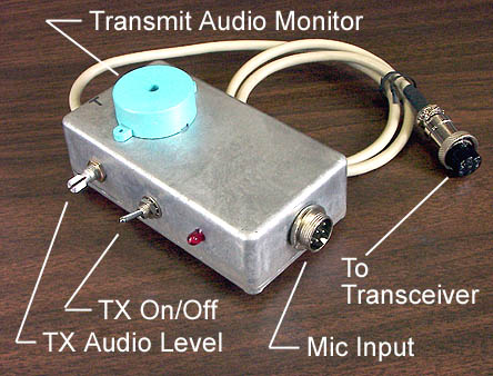
The SPST toggle switch disables the relay, preventing the interface from keying the
transmitter. The TX led still lights up when a tone is present, allowing the sound card
output to be adjusted (using the Windows mixer level controls) for positive keying without
putting a signal on the air.
I connected a surplus piezo audio transducer across the TX audio input to the interface to
provide a low-level monitor of the transmitted audio (Normally, plugging a cable into the
laptop line-out cuts off the internal speakers so the transmit tones can't be heard.) It
produces a perfect low-level side tone for the transmitted data and doesn't load the audio
line at all. (And if you want to mute it completely, stick a piece of tape over the
transducer's hole.)
Diagram 2 below shows the result of an effort to use an absolute
minimum number of components, and to improve the performance (sensitivity and keying
speed) This greatly simplified design uses an inexpensive ( approx $ .50 USD)
LM158/258/358 series dual op-amp integrated circuit to replace a lot of discrete parts
including the two transistors. This particular op-amp IC works well on a single-voltage
power supply. The input voltage range can swing all the way to the negative supply value
(i.e. ground). With the LM158 device, less than 100mV of sound card audio will reliably
key the transmitter. [ With most common op-amps, the input voltage swing can not get
closer than about 1V to either power supply value. The soundcard would then be required to
provide in excess of 1 volt of audio to trigger PTT. ]
The miniature Aromat DPDT dip-package relays shown on the schematic are sensitive enough,
and draw a low enough current through their coils, to be activated directly by the op-amp
output stage without external transistor drivers. They are also, amazingly, very cheap.
The 12-volt 1000-ohm coil version is about USD $2.50 from Digi-Key; the 5-volt
350-ohm-coil version is about $5.00
This design also keys and unkeys the transmitter much faster (an important issue if you
are using packet modes generated by MixW, the AGW Packet Engine or the
UZ7HO Soundmodem). Using a
dual-trace triggered scope, I have measured the RX-to-TX delay (time between start of tone
and PTT relay contact closure) at less than 2 milliseconds. The TX-to-RX delay (time
between the end of the tone and the PTT relay opening) is less than 3.5mS! Clearly an
insignificant addition to packet TXD overhead.
Diagram 3 below shows a modification to use the common 6-pin
dip-package 4Nxx-series opto-isolators to replace the relay. The key and unkey times are
even faster (less than 2 mS), but you lose the second set of contacts to automatically
transfer TX audio between mic and sound card. This is not an issue if you are connecting
the interface via a radio rear-panel non-mic "data" or "packet" jack.
Diagram 4 below shows a alternative approach, based on an enhanced version of the KH6TY self-powered design. This type of design requires no external DC power source. As a result, it is very convenient for use with the 6-pin mini-DIN "data" port present on many radios. An annoyance of this port is that it that does not have a DC power pin to provide power to the attached device.
Enhancements from the original KH6TY design are:
These changes allow the interface to key the transmitter on about half the audio level from the computer of the original design. The far smaller (.47uF) capacitor after the voltage-doubler charges far faster than the original 47uF one, and keys the transmitter far faster after the tone begins. Tests using the UZ7HO Soundmodem software soundcard packet TNC, show that transmissions are reliably received with only 60 milliseconds TXD (transmit delay). The original KH6TY design required over 200 MS TXD in the Soundmodem for reliable transmissions. It also now keys reliably on low-average-power modes like EasyPal "digital SSTV". (With the original design, the high peak-to-average ratio of the complex EasyPal multi-tone QAM audio subcarrier wouldn't charge the capacitor sufficiently to key the radio consistently.)
As shown, it is intended for connecting the 3.5mm 4-conductor combined stereo playback-out/mic-in jack on iPads & iPhones to the 6-pin mini-DIN "data port" present on many transceivers. The same 4-conductor "TRRS" (Tip-Ring-Ring-Sleeve) jack is present on some other devices such as Acer netbooks & various inexpensive Windows tablets. (The all-in-one audio jack was originally intended for use with boom-mic headsets for Skype, etc that used a single plug.) It is also used on some cellphones for all-in-one wired earbuds-plus-mic hookup. Often, such a 4-conductor all-in-one jack is marked with a modified version of the standard headphones icon that shows a boom mic in addition to the usual earpieces.
Modified Headset Icon Near
Jack
This type of 4-conductor 3.5mm TRRS plug was first used by analog video camcorders that combined left/right stereo audio-out and composite-video-out onto a single connector. It was also used by the 5th-generation iPod Classic that, again, output stereo audio and composite NTSC video on a single 3.5mm jack. It is also used by certain Yaesu hand-held radios that combine speaker, mic and PTT into a single jack for connecting external speaker-mics.
A shrinking number of electronics parts distributers carry a cable with this kind of plug on at least one end. It is variously known as an "analog camcorder cable", "iPod A/V cable" or "iPod multimedia cable". In all cases, the cable has the 3.5mm TRRS plug on one end and three RCA plugs (white, red & yellow) at the other end for left, right and video. If you are lucky, you will find such a cable with a right-angle plug that hugs the side of the iPad or netbook instead of sticking straight out.
A current source of this cable is Argent Data Systems (the manufacturer of the Opentracker APRS devices). Go to
https://www.argentdata.com/catalog/product_info.php?products_id=68
to order this very cable with a right-angle plug on it. Argent also offers the same cable with a straight-line plug. They also offer a two-foot cable with the two-prong 2.5mm/3.5mm plug used by Kenwood, Wouxon and Baofeng handhelds here:
https://www.argentdata.com/catalog/product_info.php?&products_id=70
This cable is essential if you are constructing these interfaces for use with these handhelds. Note that Argent offers a wide variety of other hard-to-find cables and connectors.
The self-powered VOX transmit keyer is slower than my powered design. (Packet/APRS operation requires a minimum of 60mS TXD compared to 5 mS for my active design) but has the advantage that no additional power source is required. This a real advantage when using the mini-DIN "data port" instead of a mic jack. The minimum audio level required out of the computer sound system to successfully key the transmitter is around 200 millivolts RMS, compared to just 5 to 10 millivolts for the active design. Normally one will set the computer volume controls to maximum, and adjust the transmit level (modulation) with the variable resistor in the interface. Typically "wide-open" on a computer sound system output jack will be 500-1000 millivolts RMS.
Enhancements from the original KH6TY design are:
If you choose to use the classic 600-600-ohm line transformer instead of the 2K:10K Tamura device specified on the diagram, it must be one with at least one center-tapped winding. On playback (i.e. "Transmit"), using half of the primary winding with the full secondary winding yields a 2:1 voltage step-up before the full-wave voltage-doubler rectifier doubles it again.
I have provided the text of this page and all 4 schematics as a downloadable .PDF file. This is a completely scalable vector image -- your PDF reader will scale the pages at print time to fit the current paper size specified in your print driver (if "Fit to page" is checked in the print dialog) and will produce an extremely sharp image at any size.
|
Schematics of all four versions of this design are below. These are low-res GIF graphics sized for more-or-less on-screen viewing, without excessive scrolling, on 600x800 pixel or larger screens. For highest quality printing, download the PDF containing all four diagrams in high-res vector format linked above.
Self-powered
KH6TY-based tone-key design
If you need a good inexpensive high-performance computer sound system to use with these interface designs, consider the Behringer UCA202 USB external sound system reviewed here. I have been using one of these for many years now with both the homebrew interfaces above, and with an original TigerTronics SignalLink.