 APRS VISION SYSTEM
APRS VISION SYSTEM
APRS VISION SYSTEM
 Bob Bruninga, WB4APR
 115 Old Farm Court
 Glen Burnie, MD 21060
The APRS Vision System (AVS) was developed to provide a variable bandwidth vision capability for APRS Robotic applications. The system provides an effecient method for image transmission from a mobile or rover and uses the standard APRS UI frame protocol so that the existing APRS digipeater networks can be used for vastly extended range. Using the APRS UI broadcast protocol, not only is there no wasted bandwidth for ACKS, but everyone can monitor the image. A hypothetical idea of driving a robot in New Jersey from a HAM shack in Maryland presents the concept which was so markedly demonstrated this year with the Mars Rover. The whole world watched as this tiny robot maneuvered around on the red planet. It would take an image, and then take minutes to hours to send that image back to earth, where the operators would determine their next moves.
A typical rover design would actually use full fast-scan NTSC video via an amateur television link for nearby line of sight remote control applications. But having the APRS vision system kick in when the ATV link fades would allow it to wander several orders of magnitude further away while still guaranteing a picture for control purposes. A hazardous duty rover could thus penetrate much further into a building, or in the remotest areas, and still have a viable means of visiual navigation.
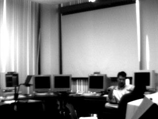
As an example, here is a LIVE view of Bob's office/lab. It is updated every 15 seconds, but you will need to reload this page to see any changes
Although the vision system is intentionally limited in resolution to fit the available APRS channels, it does provide a reasonable vision capability for remote robotics applications with the following specification:
16 level VGA compatible gray scale 1x2 aspect ratio Full picture variable resolution up to 128 by 256 Pixels
The gray scale was limited to 16 levels to reduce the transmission bandwidth and because of the limitation of VGA displays to only 16 shades of gray. The 1x2 aspect ratio was selected to maximize the wide horizontal navigational view while minimizing wasted bandwidth in the vertical. An option could allow joining two images to give a 256x256 view if needed. But the most appealing feature of the system is the variable bandwidth algorithm. This assures that only the minimum necessary picture bandwidth is transmitted, but the final resolution is under the control of the receiving station!
The variable bandwidth simply means that the first packet contains the complete image, although at very low resolution. For each doubling of the number of packets, there is a doubling of resolution. This allows the user to decide when he has enough resolution to proceed with his next step. In some cases, the single full image packet may be sufficient to allow the control operator to make the next navigation decision. If not, then he waits for 3 more packets and sees double the resolution. Then 12 packets, then 48, and finally 192 if he wants the full 128 by 256 pixel resolution. At any time the receiving station is satisfied with the image, he can send a QUIT message to stop further transmission. The results of such a variable resolution scheme are tabulated below:
LEVEL PACKET IMAGE RES DISPLAY SIZE TOTAL TIME TIME DIGIPEATED
    1     1st        8 x 16     quarter       1 sec         3 sec
    2     2-4th     16 x 32     quarter       4 sec        12 sec
    3     5-16th    32 x 64     half         16 sec        48 sec
    4    17-64th    64 x 128    half          1 min         3 mins
    5    65-192nd  128 x 256    full          4 min        12 mins
Notice that on the receive end, the poor resolution of the lower images are somewhat masked by being presented in a smaller display. By showing the poorer images at one quarter of full size, the crudeness of the rough pixels is somewhat mitigated. These imgages are presented in a zoom window which expands as the resolution increases as shown in figures 1 through 5.
Although the image in the first packet is very crude, a good example of its usefulness is a picture of a hallway where the rover is trying to decide when it has reached a turning point. In this case the operator may only need to preceive a solid color door on a white wall to make his next navigation decision. In this case, the first single packet may be sufficient. Not only does this reduce channel bandwidth by two orders of magnitude, it can also be thought of as giving a 100 fold improvement in image speed. If you can navigate on a single packet, then you can navigate at a 1 second update rate! If you need a better image, however, then your refresh time is much slower and you have to wait.
PROTOCOL: The individual packets can be thought of as arrays of pixels with dimensions as shown. Each array represents an 8 by 16 grid of boxes where each element in the array is the average value of all pixels in that box. The next array contains a similar average of all pixels in each quadrant of each box. Notice that one quadrant in each successive array can be calculated as the difference between its other three quadrants and the previous array.
                R1(x,y)            first packet
                R2(3,x,y)          next 3 packets
                R3(4,3,x,y)        next 12 packets
                R4(4,4,3,x,y)      next 48 packets
                R5(4,4,4,3,x,y)    next 192 packets
Since the array indicies are transmitted along with the packet, not only does APRS knows how to process them, but also in the case of any missed packets, the receiver can request a repeat of the missing packet.
TRANSMISSION: Normally, for real time applications, the image will be transmitted only once. But since APRS UI frames are used, some redundancy is required for the critical packets. Since the packets in each level are just a doubling of resolution over the previous level, individual packets become less and less critical to the final image. For this reason, the first packet is transmitted like any other APRS packet on a decaying time period. Like other APRS packets, once it gets down to every 10 minutes direct, or every 20 minutes via one digipeater, it will continue at that rate providing a beacon that such an image is available for anyone tuning in late.
The next three packets are transmitted on the same algorithm, but only 3 times each. Then they stop unless individually requested. The next 12 packets are transmitted only twice and all other packets are transmitted only once. Over the full image, this transmission redundancy only adds about 13% channel load.
If for some applications, continuous broadcast of an image is needed, then the image packets can be transmitted at some very low rate in the background continuously. Im not sure of the application, but if 10% of channel capacity through one digipeater was used for image transmission, then a new level 4 image could be delivered about once every 30 minutes or a level 5 image once every 2 hours. I'm not sure of the application or value of this technique, however...
WARNING: Although this system is designed for on the air use with the existing APRS networks, it is absolutely *not* intended as a means for the exchange of FAX images between fixed stations on a routine basis. The APRS bandwidth just cannot support it. It should ONLY be used in specific high priority robotic or remote vision applications.
EXAMPLES: The following images show you how the APRS Vision system works. FIrst you receive a small crude image in a single packet. Subsequent packets add additional detail until the final resolution is reached. There are 5 levels and each level requires 4 times the number of packets than the previous level.
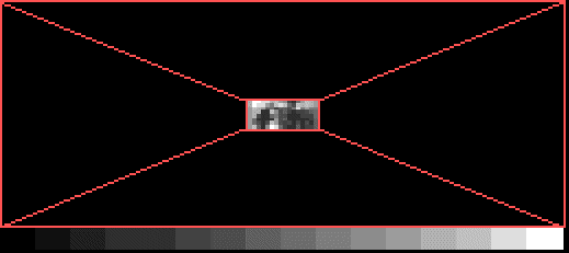
Figure 1. The first packet image at Level 1. Shown at one quarter size. It is 16x8 and 16 shades of gray.
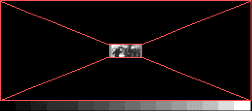
FIgure 2. After 3 more packets the image is 32x16 and 16 shades.
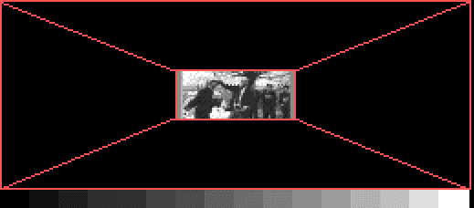
Figure 3. After 12 more packets the image is 64x32. After 48 more packets the image resolution will again double to a level 4 image (not shown).
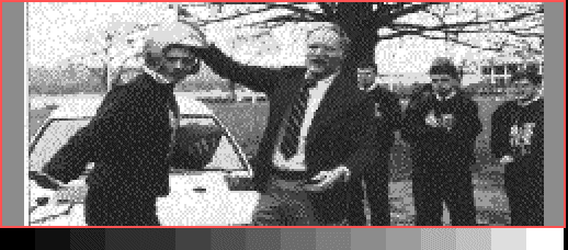
Figure 4. After 192 more packets, the full image of 256x128 pixels is displayed at full size and 16 levels of gray. This happens to be the original GPS football helmet used to track the running of the Army/Navy game football from Annapolis to Philadelphia in 1993.
Return to the APRS Homepage