 PCSAT2 Photo Gallery
US Naval Academy External ISS Experiment
US Naval Academy Satellite Lab
Bob Bruninga, WB4APR, Principal Investigator
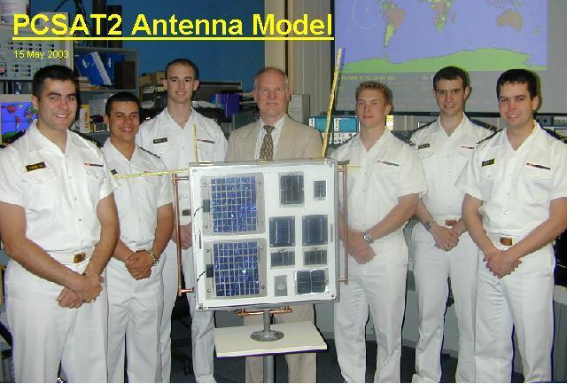
Midshipmen at Functional Test: Campbell, Lewis, Lwyn and Dendinger (Class of 06)
PCSAT2 Photo Gallery
US Naval Academy External ISS Experiment
US Naval Academy Satellite Lab
Bob Bruninga, WB4APR, Principal Investigator
Midshipmen at Functional Test: Campbell, Lewis, Lwyn and Dendinger (Class of 06)
PCSAT2 (see main page) was retrieved from the outside of the ISS and returned to Earth in Sept 2006: On 20 October, the four midshipmen, Campbell, Dendinger, Lewis, and Lwyn and I visited NRL to conduct a post-flight functional test. In the photo below, the powerful 4000 watt Sun simulator lamp is out the door behind Dendinger.

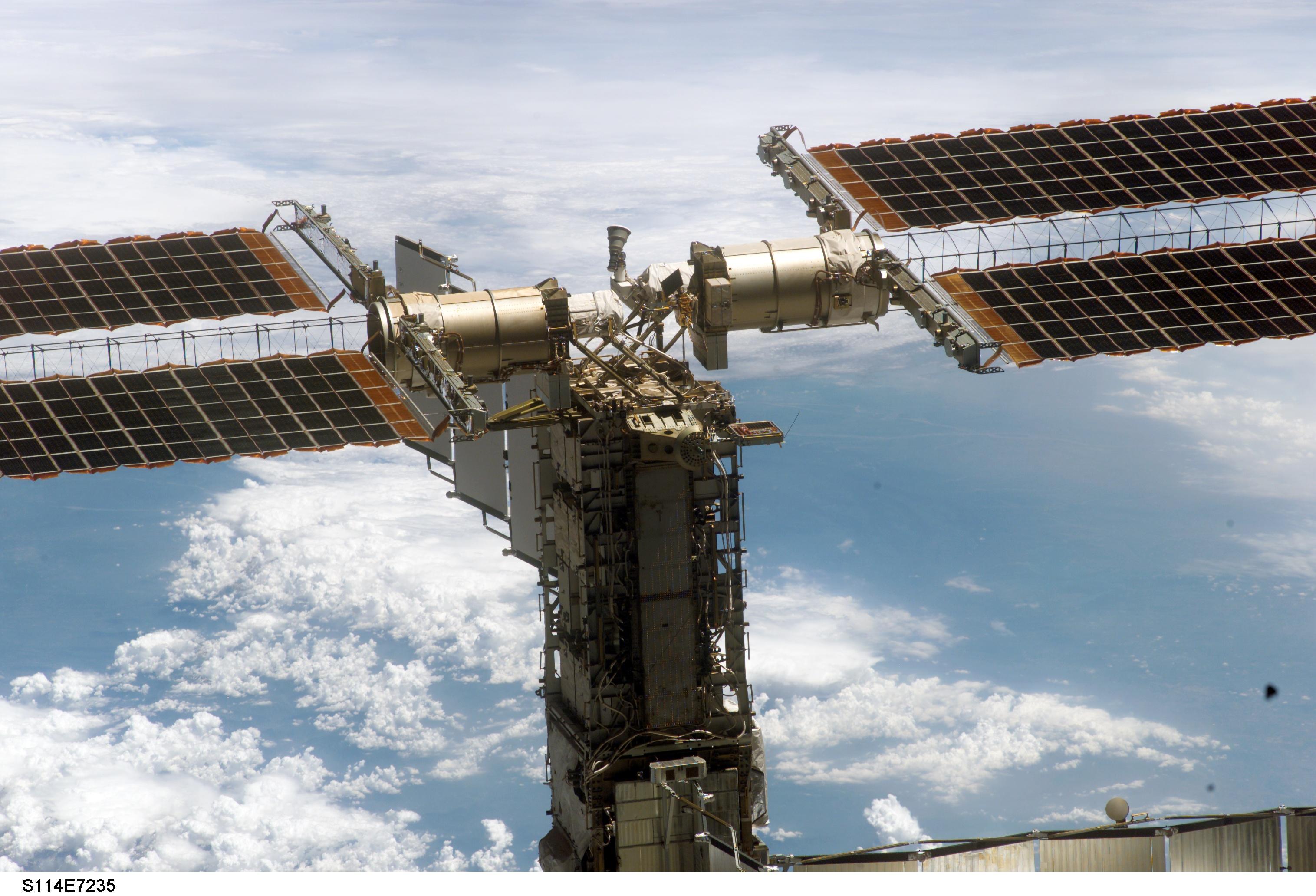
For reference, these next two photos show the installation of MISSE5/PCSAT2 on the outside of the ISS in September 2005:
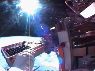
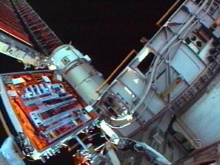
Click for great view installed and
Zoomed in view
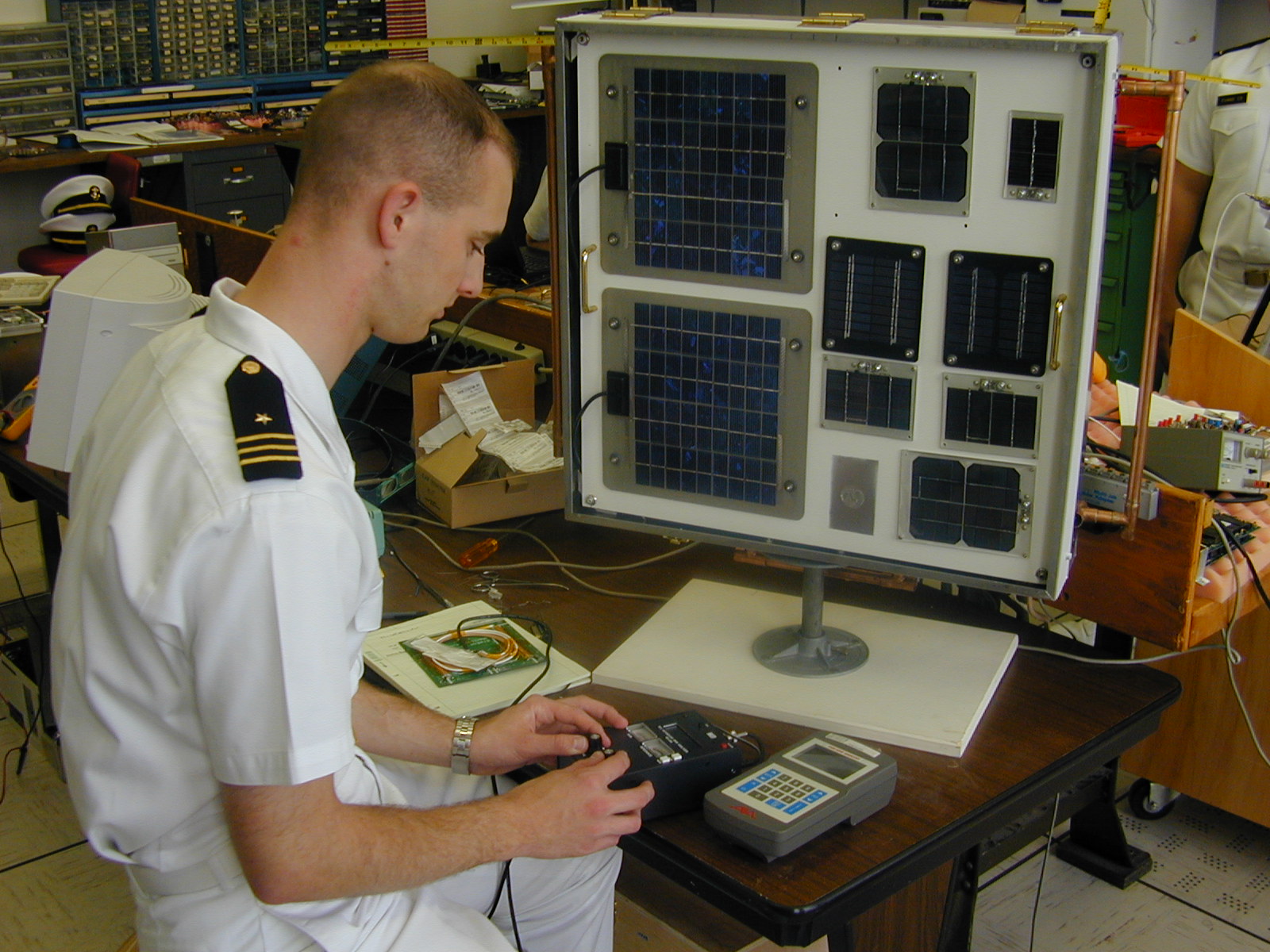
Post Flight Functional Test: The remainder of these photos are of the post-flight functional test in the clean room at NRL. Since MISSE5 hardware will fly again, it's disassembly is being done carefully and with care not to damage any of the flight hardware which may be re-used. This is the test stand so that the solar panels could be illuminated by the 4000 Watt lamp:

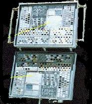
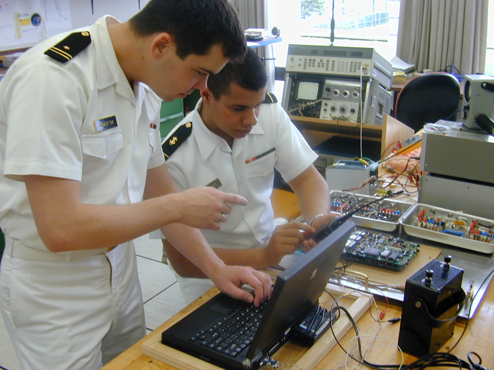
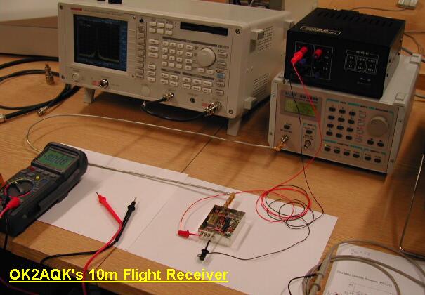
Next is the configuration of our dual briefcase ground stations that were used for telemetry, command and control during the post-flight test. The screen on the left shows the USNA command screen and the one on the right is running Hyperterm to capture the 9600 baud science data:

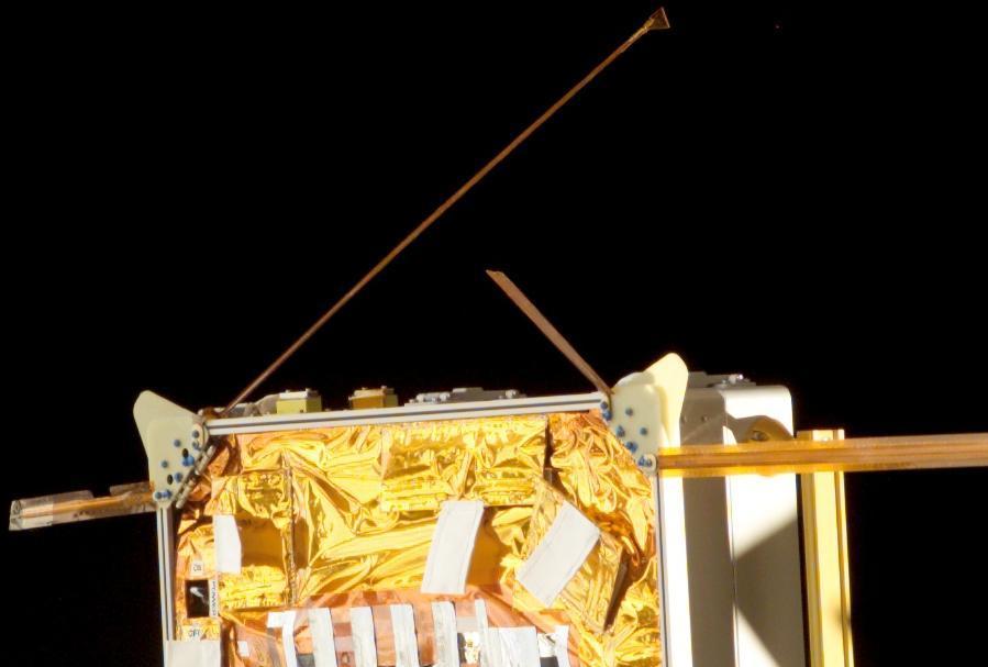
The next photo shows the PCSAT2 side of the system and if you look in the upper left corner you will notice the missing VHF antenna that "broke off" in the astronauts hands as he was manipulating it to fold it under the MLI blanket for return to Earth.

You can see where the antenna broke at the sharp double-90 degree bend that was a last minute bend by the spacecraft integrators to assure the antenna would not abrade against the main solar cells when it was in its folded launch configuration. This double-90 degree bend in the brittle berilium copper antenna assured a stress and fracture point susceptible to fatigue damage.


There was some visible damage to the solar arrays after 1 year on orbit and the following photo shows the largest impact hit on one of the solar cells.

Two of our typical low cost (2-cents-on-the-dollar) solar cells were flown and only appear
slightly clouded after a year in space. This matches our experience after 5 years on
orbit of the same cells on PCSAT1 that appear to have lost only about 30% of their
beginning-of-life performance over the 5 years. The other commercial panel we flew
had clouded up 100% during ground testing even before flight and was useless.

Another interesting observation was the slight fogging of the Kapton tape on the tip of the antenna as shown in the photo below. The tip on the right is compared to a new strip of the same tape (pressed onto the stainless steel table for comparison). Also note the absence of fogging on the main antenna Kapton Tape which is a special coated version to better withstand the atomic oxygen on orbit.
PCSAT2 OPERATIONS: Other operations photos are shown on the PCSAT2 Operations web page
ORIGINAL PRE-LAUNCH / DESIGN PHOTOS FROM THE ORIGINAL PCSAT2 DESIGN PAGE:
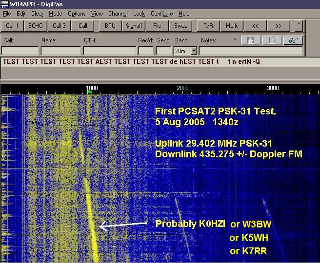
The first PSK signal heard through the PSK-31 Transponder:
This image below (25% resollution) is the actual mounted position (in the center facing up):

Click for full rez (1 Meg)
Another full rez big view (Lots of station hardware(1 Meg)
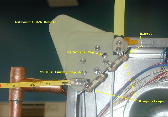
PCSAT2 Antenna angles (various!)
and all the station blockages underneath in the RF keep out zone sketch
The original team of midshipmen involved in the project:
Other midshipman photos: PCSAT2 prototype,
Antenna SWR measurements,
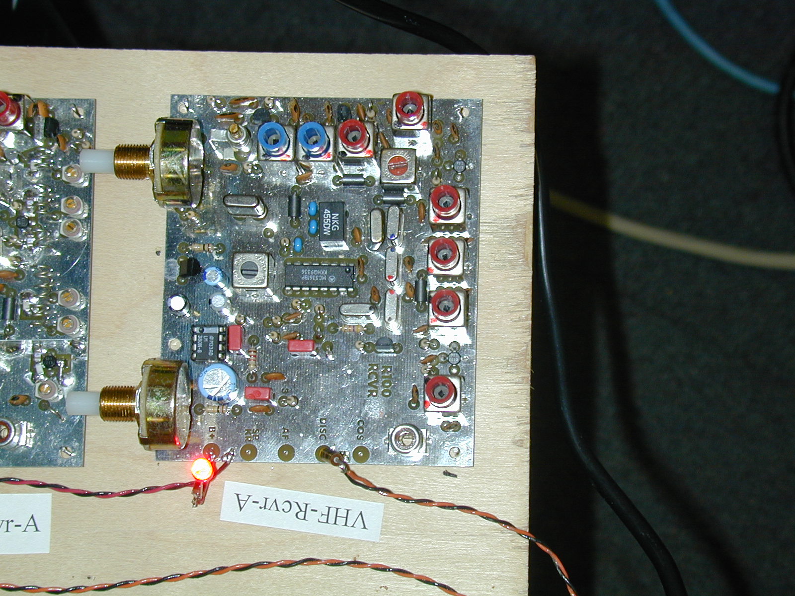
Radio configuration.
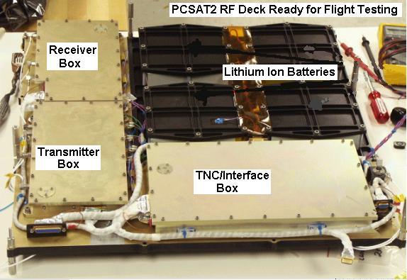
The PCSAT2 communications System configuration for flight:
PCSAT2 TELEMETRY SCREEN: The screen below shows what the PCSAT telemetry screen looks like. Whenever PCSAT2 is on the air, even on the ground in testing, you can monitor the APRS worldwide Internet system and see it.

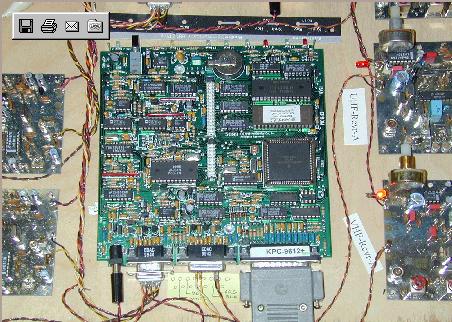
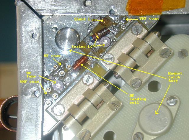
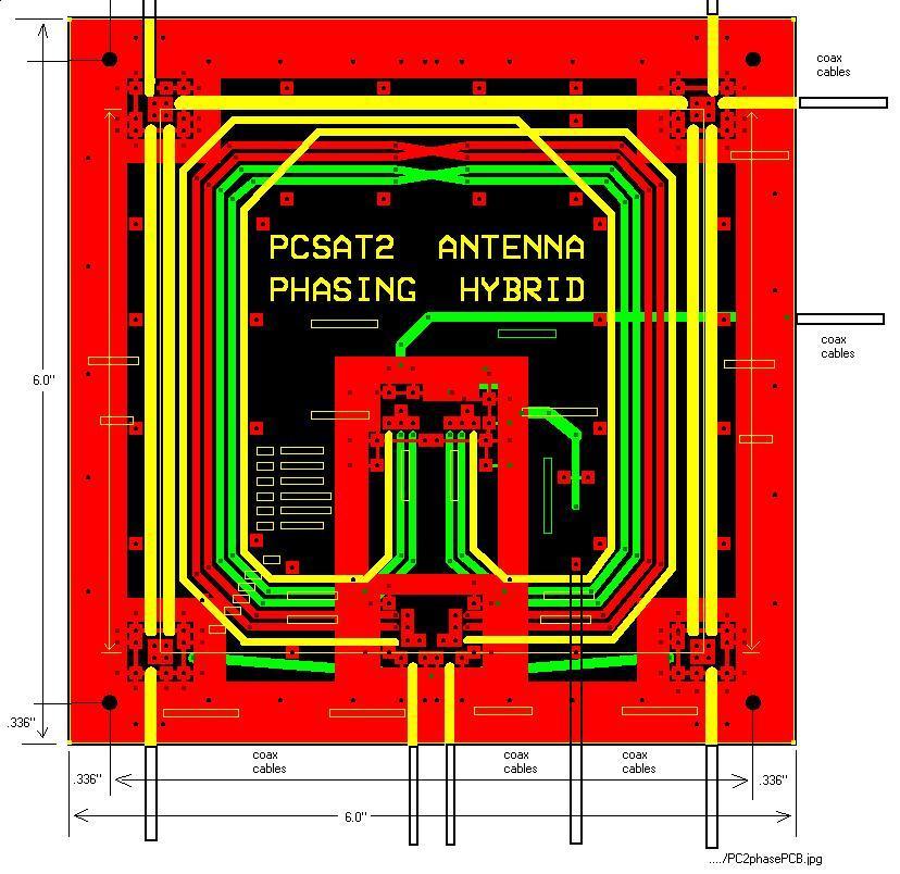
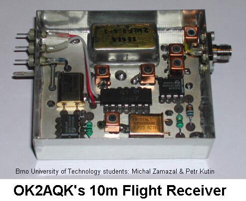
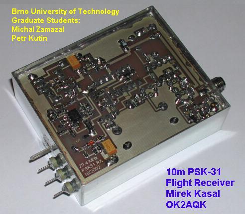
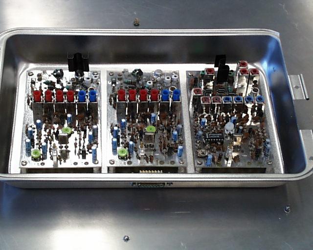
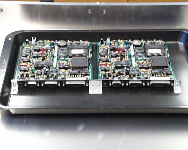
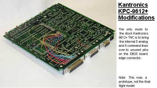
PROTOTYPE Circuit Boards:
Here are several additional PHOTOS, DRAWINGS and Documents:
You are visitor:
<== not visible on IE, but NetScape sees it
.
|
|
|
|