 LAD-C / PCSAT3 Comms Proposal
ISS Debris Detection Experiment LAD-C
US Naval Academy Satellite Lab
Bob Bruninga, WB4APR, POC for comms
LAD-C / PCSAT3 Comms Proposal
ISS Debris Detection Experiment LAD-C
US Naval Academy Satellite Lab
Bob Bruninga, WB4APR, POC for comms
LAD-C Telemetry/Comms System: This page addresses the telemetry and communications proposal for LAD-C. Since this proposed communications system has flown before on ISS as PCSAT2 , this proposal is called PCSAT3.
LAD-C: is an experiment for detecting the collisions of space particles impacting the ISS. It consists of three parts, an aerogel collection array for capturing particles, an accoustic experiment (called Pindrop) to pick up the vibratinos of each impact and a proposed communications downlink experiment called PCSAT-3. This page only addresses the specific details of the PCSAT3 communications portion of the experient.
Since this is a space environment experiment, the downlinked data will be of interest to students, schools, and the Amateur Satellite community around the world. The public and educational nature of the experiment, plus its communications capablities make it a viable project within the special rules of the international Amateur Satelllite Service. It would support educational and student outreach objectives of both AMSAT, ARRL and NASA as well as provide telemetry on the debris impacts. Students and schools may enjoy monitoring the data directly from their school satellite stations and hearing these impacts.

The image above is just a representative concept sketch from an existing aero-gel debris capture system with the Pindrop acoustic concept added. Whatever the structure ends up being, the comms package and data downlink experiment is added with little impact to the LAD-C. Current design concepts will use Space Station power via one of the external camera ports. The antennas needed are only 19" and 6" whip antennas.
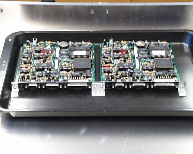
The image below is representative of what PCSAT3 Comms hardware would look like. This particular photo shows the PCSAT2 Comms payload which was attached to the backside of the MISSE5 experiment in the same manner. In PCSAT2, the 4 large batteries were 20-times overkill but needed on that mission for heaters for the science experiment.
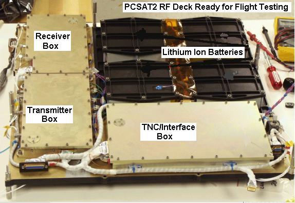
The antenna requriements for the comms payload are very modest and consist of two or four "tape-measure" type antennas as shown below on PCSAT2. Their flexibility makes them immune to damage and also safe for any nearby astronauts.

The LAD-C/PCSAT3comm system would operate in the ITU Amateur Satellite Service in cooperation with ARISS and provide a multi-user communications transponder so that it complies with the ITU rules as shown in an example below. See the Paper on PCSAT's operation in the Amateur Satellite Service or the Full ITU rules as published by the IARU .
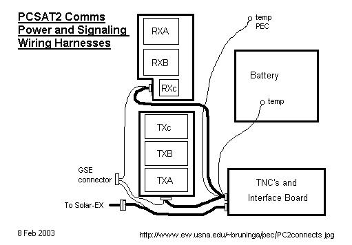
SPONSORING ORGANIZATION: The Telemetry/Command/Communications project for LAD-C/PCSAT3 would be conducted under the USNA Small Satellite program. Since LAD-C/PCSAT3 would fly on the ISS, its operations would be fully coordinated with the ARISS (Amateur Radio on the ISS)international team. The block diagram below describes the comms payload:

LAD-C COMMS PAYLOAD DESCRIPTION: The LAD-C comms payload would use the same dual redundant AX.25 command and control system as used on PCSAT2 offering 8 on/off commands, 20 telemetry channels and a bi-directional 9600 baud serial port for the debris detection data collection system. Similar to PCSAT2, the 9600 baud downlink can provide over 3 Megabytes of data per day to the existing volunteer system of internet linked automated ground stations that have served PCSAT1 and PCSAT2 over the last severl years. It also supports the Digital Comms Relay support of the PCSAT/APRS mission.
DOWNLINKS: The PCSAT3 downlink must not interfere with ARISS activity on ISS and so it must operate on UHF when the crew is using the ARISS system for school communicaitons. The rest of the time, PCSAT3 can operate on VHF where there is a 9 dB link advantage. The diagram above shows how the two downlink systems have VHF and UHF transmitters with the default being UHF. Under crew control, these two transmitters can be switched to VHF as needed. Since LAD-C is powered from the ISS external camera port, its transmitters are under the direct control of NASA or the crew for astronaut safety or to avoid any interference with existing ARISS communications.
UPLINKS: Uplinks would be on 10 meters in the 29 MHz satellite band. There are no other emitters on ISS in this band that would cause any interference.
CREW AND EVA SAFETY CONSIDERATIONS:
To provide for EVA Safety, PCSAT2 had to be on/OFF commandable for every EVA and Russian docking evloution. This was a coordination burden for NASA, the Space Test program and USNA operations personnel. For the LAD-C payload, however, which attaches to an external camera mount, we would use the crew-controlled camera power switches to allow the crew direct and immediate internal control over the trnamsitters on LAD-C. The diagram below shows how we intended to use these 4 on/off switches to give the crew functional control over the payload.
HARDWARE AND DESIGN DETAILS:
These detail designs all come from the PCSAT2 system, but are presented here as representative of the kinds of circuits proposed for LAD-C.
TELEMETRY SCREEN: The screen below shows what the PCSAT3 telemetry screen could look like. Whenever PCSAT3 is on the air, even on the ground in testing, you can monitor the APRS worldwide Internet system and see it.

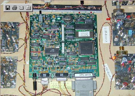
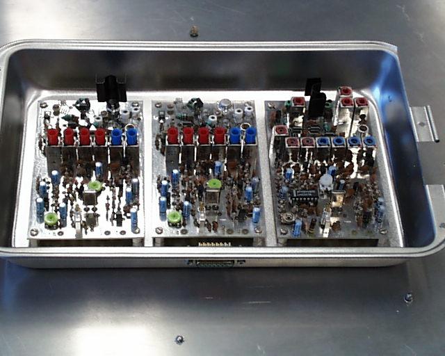
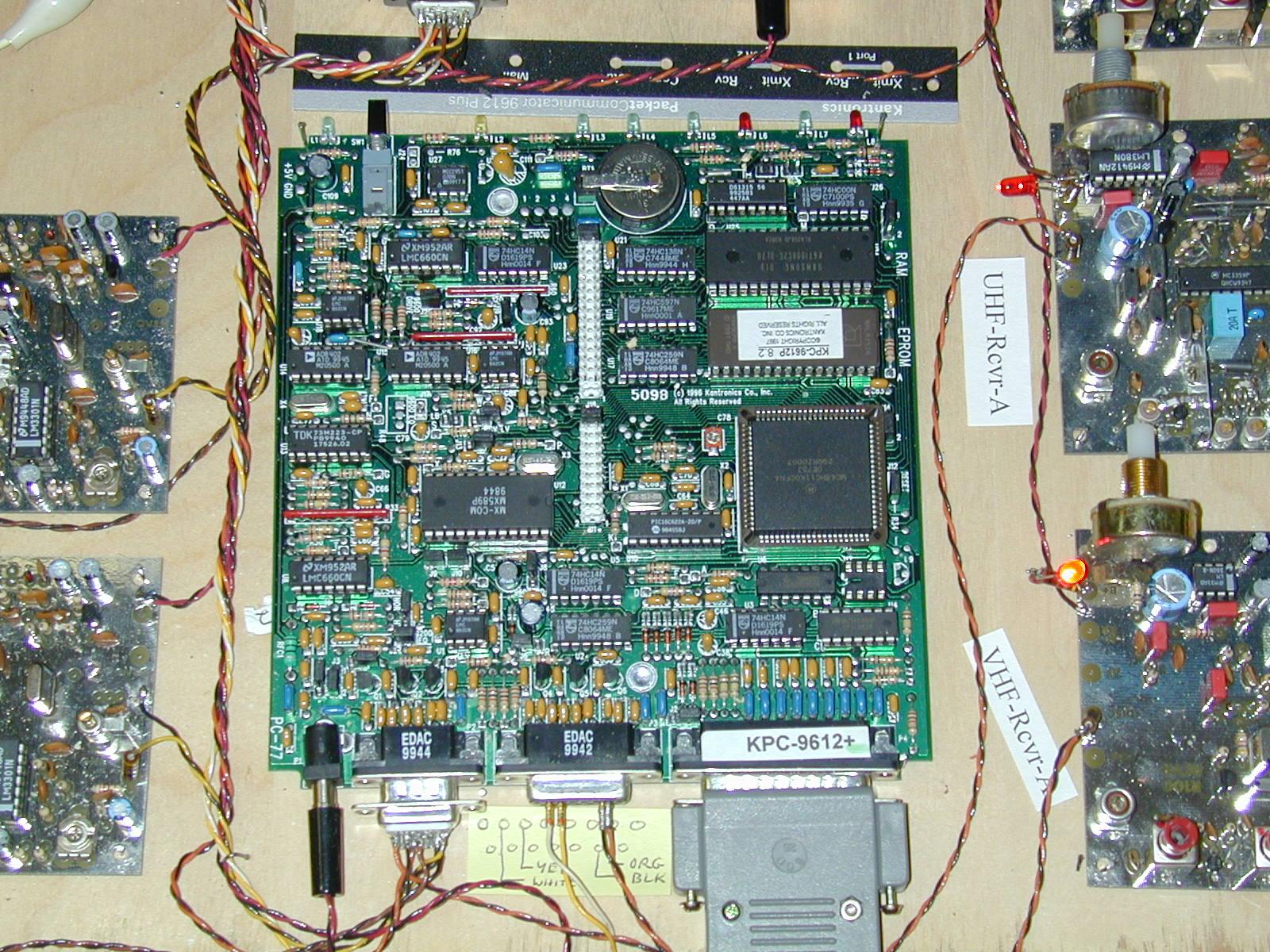
PROTOTYPE Circuit Boards:
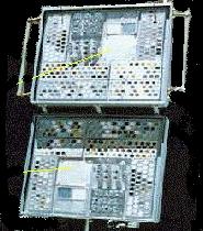
The TNC COMM system (one of 2) and the dual receivers and dual transmitters.
The digital communications relay will operate within the ITU regulations for educational/outreach operations in the Amateur Satellite Service, to provide simple Satellite digital communications for amateur satellite operators and educators and possible remote environmental sensors worldwide Examples . This comms mission will provide a follow-on extension to the educational communications mission of PCsat, Boats at sea, cross country travelers, expeditions, or other travelers far from existing APRS terrestrial communications infrastructure. The Transponder and LAD-C data is captured by existing PCsat-to-Internet ground stations and fed into the existing worldwide internet linked APRS system. The LAD-C mission would join ISS, MIR, PCsat and several other on-orbit experiments (ASTARS) that have been conducted over the years leading up to this exciting capability.
Here are several additional PHOTOS, DRAWINGS and Documents:
The AX.25 segment of the PCSAT2 communications mission has been demonstrated a number of times in space via PCsat, MIR School tests, the Shuttle SAREX, and the SPRE mission. . It is also a spin off of a previous launch opportunity that we had in 1998 called NATSweb that almost got launched on SEA-LAUNCH.. The PCSAT2 Communications mission is a project to produce a viable external ISS payload in a very short time frame using off the shelf components where possible. Here are the background topics of design:
APRS is the Automatic Position Reporting System that the Naval Academy uses for tracking its boats and a variety of other vehicles and networks using the APRS Automatic Position Reporting System . The PEC Communications transponder would be operated under the rules of the Amateur Satellite Service and the rules of the FCC.
You are visitor:
.
|
|
|
|
